Some Interesting Lesser Used Joints –
This is an excerpt from “The Woodworker: The Charles H. Hayward Years: Volume III” published by Lost Art Press.
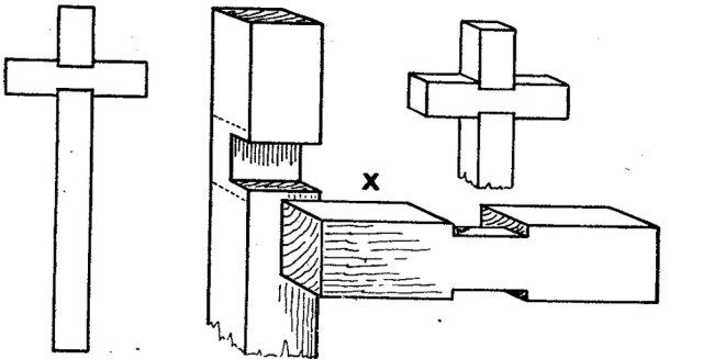
CROSS HALVING WITH HOUSED SHOULDERS
The cross-halving joint, with notched or housed shoulders (Fig. 1), is only rarely used in actual practice. In ecclesiastical woodwork it is occasionally seen on a cross, and at times (though less frequently) in outdoor woodwork framing when the timbers are fairly stout.
The cutting of the joint is shown at X. The notching (or shoulder) is never more then one-sixth of the width, and is sometimes less. Although the cross piece is slightly weakened by the shouldering, the joint is really a strong one as in gluing there is an extra hold at each side. The joint moreover is a neat one and has been used effectively for high-class joiner-made estate gates.
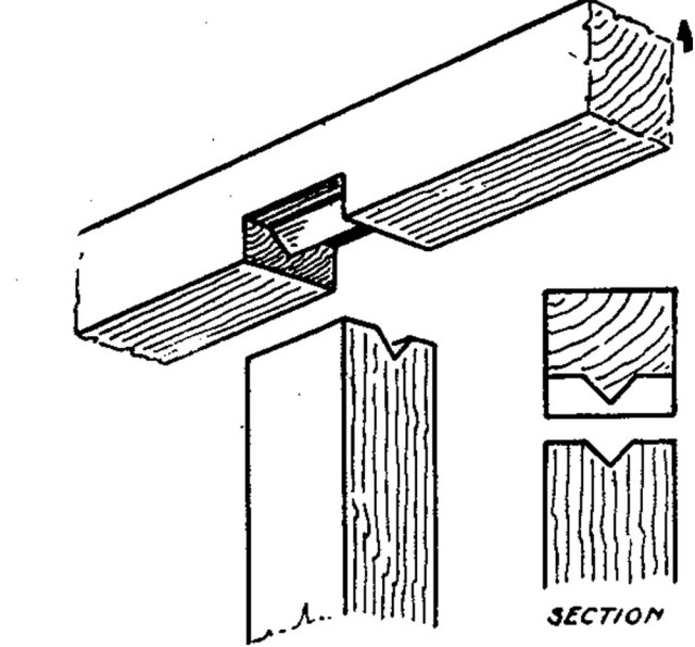
SADDLE JOINT
For this Joint (Fig. 2). the name “saddle” is distinctly obvious, especially if it is turned the reverse way; the V-shaped aperture in the post fits saddlewise on the triangular projection in the notching. The joint is used to connect upright posts to sills, or to the head horizontals of similar framing.
In everyday outdoor work it may be hardly worth the additional labour, but for indoor joinery it is a good joint. It weakens the framing much less than a mortise and tenon joint, and there is little effect of shrinkage on it. Its great advantage is that the saddle (the V) keeps everything in alignment. Depth of notch in sill should not exceed one third or two-fifths of the thickness of the timber.


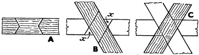
DOVETAILED SCRIBED OR HALVED JOINT
This (Fig. 3) is a joint which, in former days, was used in better class interior woodwork when pieces of timber had to be lengthened.
When accurately marked and cut the double dovetails ensure against any gap showing. In Fig. 4 the separate parts are shown in plan and elevation. Sections at both ends of the joint (A and B) are also indicated. From these diagrams the setting out of the joint can be followed. For general building the double dovetail involves too much work to justify its general use and it is rarely seen. In the Handicraft Centre, however, the joint has often been used as an exercise, and the home worker who has a flair for accuracy in marking and cutting would enjoy a couple of hours on it.


THREE-WAY HALF-LAP JOINT
The rather complicated three-way halved joint at Figs. 5-8 is one of the most troublesome to mark out and construct with flawless accuracy. It has always been widely used by pattern makers, chiefly for the lap-jointed arms of pulley patterns.
In former days, however, the village carpenter knew it and used it for barrow wheels. Fig. 5 shows a wheel with built up rim (the joints probably bridled). Fig. 6 shows the three arms, or spokes, lap-dovetailed to the rim and “three-way lapped”, or, as it is sometimes termed, one-third lapped, together. The separate arms cut and ready for assembling are shown at A, B, C, Fig. 7. For clearness piece C is shown reversed—that is, upside down.
If the centre joint part of Fig. 6 is drawn full size it is worth while setting out the parts. Take the width of arm as, say, 2 ins., and the thickness 1-1/2 ins. Two points may be noted as a guide.
On the width face all the lines can be set out with T square and 60 degree set square. The thickness (1-1/2 ins.) is divided into three in order to get the three planes or steps of the joint. Hence the term “one-third” lapped.
Fig. 8, in conjunction with Fig. 7, will show how the parts are assembled. The “step” of piece A is 1/2 in. thick, the edges of the cut part above being 1 in. Over this B lies at an angle. It covers the flat step of A, but leaves two little triangular gaps (x) (Fig. 8) which are later filled by the corresponding triangular steps marked on C, Fig. 8.
Piece C (shown reversed) rests at the correct angle on the halved upper face of B, the little mid-step projections fitting into the gaps (x) left on Piece A. The piece C is the same as A except for these extra triangular steps (x).
When the parts are glued it will be seen how firmly they are interlocked. Incidentally, if the reader can lay his hands on a medium-sized turnip, it is an interesting study to make a small experimental model joint with a penknife. The parts need not exceed 1 in. by 3/8 in. It is not the first time that turnips have been used for model joints.
— MB